Emergency Pacing
Emergency Pacing
Authors: Lynn P. Roppolo, MD, Assistant Professor, Division of Emergency Medicine, University of Texas Southwestern, Parkland Memorial Hospital, Dallas, TX; Gregory Keelen, DO, Division of Emergency Medicine, University of Texas Southwestern, Parkland Memorial Hospital, Dallas, TX; and Robert B. Simonson, DO, Clinical Assistant Professor, Division of Emergency Medicine, University of Texas Southwestern, Parkland Memorial Hospital, Dallas, TX; Associate Medical Director, Emergency/Trauma Services, Methodist Medical Center, Dallas, TX.
Peer Reviewers: Sandra M. Schneider, MD, Professor and Chair, Department of Emergency Medicine, University of Rochester School of Medicine, Rochester, NY; and Lawrence C. Brilliant, MD, FACEP, Medical Director, Department of Emergency Medicine, Doylestown Hospital, Doylestown, PA.
A pacemaker is an electronic device that provides an electrical signal to stimulate the heart beat when the intrinsic pacemakers fail. The development and implementation of cardiac pacing and pacemaker generators has been well described and documented in many publications.1-5 Modern cardiac pacing systems have evolved dramatically over the past 50 years, beginning with Callaghan and Bigelow in 19516 who successfully used transvenous pacing on hypothermic dogs, to Zoll's use of DC current transcutaneously in 19524 to pace humans, and continuing with Swan and Ganz in 19707 who used a balloon-tipped catheter to float pacing leads into the heart.
Patients requiring emergency pacing may present with malfunction of an existing permanent pacemaker or a new arrhythmia requiring emergent intervention. Proper implementation of emergency cardiac pacing is a skill every emergency physician should learn. Consultation with cardiology often is required in such situations but may not be available immediately. This article will attempt to provide a practical overview of emergency pacing with an emphasis on temporary pacing and implications for the emergency physician. Permanent pacemaker and implantable defibrillator (ICD) malfunction will be discussed briefly; however, a detailed discussion of these devices is beyond the scope of this review.
The Editor
Pacing Technology
Definitions. An ampere (amp) is a unit of electric current (I). The units for pacemakers are expressed in milliamperes (mA) because the current in a pacemaker is so low. A volt (V) is the unit to express the electromotive force that causes current to flow. Resistance (R) is the opposing force to the flow of current. Ohm's law defines the relationship of voltage to current and resistance and is defined as V = IR (voltage is equal to current multiplied by resistance. Impedance is the more appropriate term used for resistance in a pacing system. The anode of a device is the terminal where current flows in. The cathode of a device is the terminal where current flows out. Anode/cathode is not the same as positive/negative or vice versa.
Pacing Systems. A pacing system consists of an electrical circuit in which a battery provides electricity that travels through a conducting wire to stimulate the myocardium. There are two main components to a pacing system: a pulse generator, which encases the battery, and pacing leads. Most of the pacemaker's battery power is dedicated to stimulating the heart with a pacemaker spike. A small portion of the battery power is for sensing and the timing device of the pacemaker. The pacemaker lead conducts electricity from the pacemaker generator (i.e., battery) to the heart. It is responsible for sensing intrinsic cardiac function as well as providing an electrical stimulus for contraction.
Endocardial pacing leads may be bipolar or unipolar, referring to the number of electrodes manufactured on the lead that is implanted in the heart. Most modern systems are bipolar, with a cathode and an anode located at the tip of the lead that keeps the electrical circuit (current flow) within the heart. The unique difference with unipolar leads is that the anode is located on the surface of the pulse generator, which creates a longer circuit for conduction. The battery in the pacemaker box generates current that passes through the pacemaker wire (or lead) attached to the negative terminal through the myocardium and back through the other wire connected to the positive terminal to complete the circuit. Distinguishing between the negative and positive electrodes is important so that the wires are connected appropriately to the pulse generator. Although the lead connections typically are labeled with temporary pacing systems, in the excitement of an emergency situation, no clinical problem usually results if the leads are reversed.8
The primary function of the pulse generator is to supply sufficient energy to the heart muscle to stimulate a contraction. Pacemaker energy output is dependent upon the signal amplitude and pulse width. Signal amplitude is measured in electrical units of volts or milliamperes (mA). It is the amount of energy delivered by the pulse generator with every pulse to initiate cardiac depolarization. Pulse width is the width of the pacemaker spike in time (output duration) and is measured in milliseconds. The electrical pulse has to be strong enough and last long enough to capture the myocardium. For proper permanent pacer operation, signal amplitude and width are set high enough to reliably achieve capture of the myocardium, yet low enough to prolong battery life. A typical permanent pacemaker has a pulse width of 0.5 second. The pulse width of temporary pacemakers usually is fixed at 2.0 seconds and is not typically a programmable function. The initial output setting depends on the mode of pacing and is discussed in the section on temporary pacemakers. The atrial chamber, the ventricular chamber, or both chambers of the heart can be paced. Pulse generators for dual-chamber pacemakers have separate atrial and ventricular output controls.
Setting the rate on the pulse generator determines the number of stimulations to be delivered per minute. The rate setting depends on both the patient's condition and the reason for pacing. In patients who have had cardiac arrest, the initial rate typically is set at 80 beats per minute. Pacing rates for overdrive suppression of tachydysrhythmias may greatly exceed these values. The heart rate on a patient's rhythm strip never should be lower than the patient's set pacemaker rate.
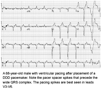
Capture is both an electrical and a mechanical event. The ability of the electrical impulse to initiate a cardiac response can be evaluated on electrocardiogram (ECG). Electrical capture is indicated by a pacer spike followed by a corresponding P wave or QRS complex, depending on which chamber is being paced. If the atrium is paced, the spike appears before the P wave. If the ventricle is paced, the spike occurs before the QRS complex. (See Figure 1.) The pacemaker causes the heart to depolarize in an artificial fashion resulting in widened P waves and QRS complexes. A pacer spike without a corresponding P wave or QRS complex indicates failure to capture. Mechanical capture exists when the pacer spike and its corresponding QRS complex are followed by a cardiac contraction. The presence of mechanical capture is assessed by palpating a pulse that corresponds to the set rate. Recently ultrasound has been used successfully to determine the presence of mechanical capture.9-11 It is imperative that one assures that mechanical capture has occurred when electrical capture is seen.
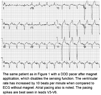
Pacemaker sensing refers to the ability of the pulse generator to detect and recognize the intrinsic cardiac impulses. To synchronize the beats, the generator first analyzes the intrinsic rhythm and then stimulates the heart only as needed. Pacemaker generators can be programmed to deliver an impulse to the ventricle each time an atrial beat is sensed, or they can be set to stimulate only when no intrinsic beat has been detected during a predetermined interval. Atrioventricular sequential pacers provide synchronization between the atria and the ventricles for optimal cardiac output. Failure to sense occurs when the generator does not recognize the intrinsic cardiac impulses. Placing a magnet over the pulse generator typically will turn off the sensing mechanism and convert to an asynchronous mode of pacing. (See Figure 2.)
Pacemaker Code
In 1974, the American Heart Association originally proposed the use of a three-letter coding system to describe the functions of various pacemakers. This code has been expanded to a five-letter system by the North American Society of Pacing and Electrophysiology (NASPE) and the British Pacing and Electrophysiology Group (BPEG), which now is referred to as the NBG code (combining NASPE and BPEG). The emergency physician should be familiar with the first three positions that commonly are used and fundamentally are more important. (See Table 1.) The fourth position refers to programmability of rate modulation and the fifth position is reserved for devices that have an antitachycardia function. An R may be placed at the end of the three-letter designation if rate modulation is an option with the device.8
| Table 1. Pacing Codes |
 |
The third position can be confusing and represents the programmed response to the sensed event. An "I" in this position indicates that a sensed event inhibits the output pulse. The triggered mode (indicated by the letter "T" in the third position) means that an output pulse is triggered in response to a sensed event. "D" is a designation used for dual-chamber systems and means that both "T" and "I" responses are possible. An event sensed in the atrium inhibits the atrial output but triggers a ventricular output. There may be a delay between the sensed atrial event and the triggered ventricular output to mimic AV synchrony or a normal PR interval. If a native ventricular signal or R wave is sensed, the ventricular output and possibly even the atrial output are inhibited, depending on where sensing occurs.
In patients with single-chamber ventricular pacemakers, the VVI mode most often is encountered. In the VVI mode, the ventricle is paced at the programmed rate unless a ventricular event is sensed, in which case the next paced event is inhibited.12 The most common mode for dual-chamber pacemakers is DDD.12 The DDD pacing mode is more physiologic and combines the functions of ventricular, atrial, AV sequential, and atrial synchronous pacing. A detailed discussion of types of permanent pacemakers is beyond the scope of this text.
Permanent Pacemakers and ICDs
The pulse generator for permanent pacemakers consists of a lithium iodine battery that is small, long-lasting, and has a gradual energy depletion that can be monitored closely. They typically are implanted in a prepectoral pocket located in the infraclavicular area. The lead is connected to the pulse generator and passes through the central venous system to the right side of the heart where the tip is located at the apex of the right ventricle. A second lead is placed in the right atrium for dual-chamber pacemakers. The leads may be unipolar or bipolar (more common). The advantages of a bipolar system include less interference from extraneous signals being sensed as a cardiac event. Newer, still-experimental pacing systems may have two atrial leads, one in the right atrial appendage and the other either in the coronary sinus or at the os of the coronary sinus, with the ventricular lead in the right ventricle, either at the apex or at the outflow tract. This dual site or biatrial pacing system is used to prevent or minimize bouts of atrial fibrillation.13 Another still experimental system is biventricular pacing with two ventricular leads, one in the right ventricle and the other in a venous branch of the coronary sinus.13 Epicardial leads can be implanted surgically onto the heart's surface. These usually are used in children, since implanted endocardial leads eventually become too short as children grow.
Indications for a permanent pacemaker include a variety of conditions resulting in symptomatic bradycardia. Biventricular pacing may be used in individuals with dilated cardiomyopathy to improve cardiac function.14
All implantable cardioverter defibrillators (ICDs) are also ventricular pacemakers for bradyarrhythmias. Basic components are similar to that described for a permanent pacemaker except that ICDs have a high voltage capacitor and a complex microprocessor memory. The right ventricular lead is used for sensing and pacing. If dual-chamber pacing is required, a second lead is placed in the right atrium. For defibrillation, a biphasic waveform is preferred because it is more effective at lower energies compared to monophasic waveforms. Whereas external defibrillators deliver a maximum of 360 J, the maximal output of an ICD for defibrillation is about 30 J in most units.
Permanent Pacemaker Malfunction
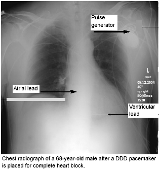
Patients with a malfunctioning pacemaker may present with weakness, dizziness, malaise, recent pacemaker placement, or manipulation. The history should include critical information about the pacing unit during the assessment. Patients with permanent pacing devices are provided with a wallet card that contains identifying information about their pacemaker. An ECG and chest radiograph are critical to the evaluation of any patient with a pacemaker problem. A chest radiograph should evaluate the pulse generator and positioning of the leads. (See Figure 3.) The emergency physician should be familiar with the different pacing modalities to determine the expected associated ECG findings.
| Figure 3. Chest Radiograph Confirming Pacing Lead Placement |
|
|
The most common causes of pacer malfunction can be divided into three general categories: failure to capture, inappropriate sensing, or inappropriate pacemaker rate. The most common cause for permanent pacemaker malfunction is inappropriate sensing followed by failure to capture.15
The sensing ability of the pacemaker is influenced by the sense amplifier of the pacemaker and the signal detected at the pacing electrode within the heart. Undersensing may be due to lead displacement, inadequate lead contact, or lead fracture. It may be related to the programming of the pacemaker in the presence of low intrinsic P waves or QRS complexes. The pacemaker may oversense by misinterpreting extracardiac signals or tall T waves for QRS complexes. For example, muscle twitching such as the pectoralis may be sensed by the pacemaker as a ventricular or atrial contraction. Oversensing may manifest as irregular pacing or apparent complete absence of pacemaker function. Undersensing may present with the appearance of pacemaker spikes occurring earlier than the programmed rate. The spike may not be followed by a paced complex if it occurs during the refractory period.
Failure to capture may present as either a complete absence of pacemaker spikes or pacemaker spikes not followed by a stimulus induced complex. This may be due to battery depletion or a lead problem such as loss of contact due to disconnection, a break, or displacement. Failure to capture also may be due to an exit block that is the consequence of a high stimulation threshold resulting in a failure to pace despite an adequate stimulus. This most commonly is due to changes in the endocardium in contact with the pacing system from a variety of etiologies such as ischemia, hyperkalemia, and class III antiarrhythmic drugs (e.g., amiodarone).
An inappropriate pacemaker rate occurs when the pacing rate is below or significantly above the programmed rate of the pacemaker. The most common cause of a low pacing rate is battery depletion that does not occur abruptly with lithium iodine batteries. Paced tachyarrhythmias in patients with permanent pacers are rare but may respond to magnet application which can convert the pacemaker to a fixed rate and terminate the tachyarrhythmia.16 Electromagnetic interference, primarily in the medical environment, is another important cause of pacemaker malfunction. Sources include surgical electrocautery, therapeutic radiation, cardioversion/defibrillation, and magnetic resonance imaging. Potential clinical consequences include bradycardia, asystole, tachyarrhythmias, impaired cardiac output, and endocardial injury.12
Life-threatening emergencies secondary to permanent pacemaker malfunction are rare due to better technology and close follow-up of these patients. In the vast majority of cases presenting to the ED, cardiology consultation (preferably an electrophysiologist) will be required to interrogate the pacemaker. To quickly test for failure of the output circuit, a magnet can be placed over the pacemaker. Magnet application closes a reed switch within the pacemaker causing it to bypass the sense amplifier and induce asynchronous pacing. (See Figure 2.) If the pacer demonstrates appropriate magnet-induced behavior, the output circuit is working and it may be oversensing. A decrease in the predicted rate after magnet application is concerning for battery depletion. In patients with symptomatic bradycardia or asystole, advanced cardiac life support (ACLS) guidelines should be followed if magnet application fails to restore hemodynamic stability. If external pacing is utilized, the pads should be placed at least 10 cm from the internal pacemaker. A transvenous pacemaker usually is not necessary and may be difficult in these patients without fluoroscopic guidance. Furthermore, blind insertion of a transvenous pacemaker may cause displacement of the permanent pacemaker leads.
Electrical defibrillation can be performed in patients with a pacemaker as long as the paddles also are placed at least 10 cm from the pulse generator. Pacing parameters should be re-evaluated by an electrophysiologist if the resuscitation is successful as defibrillation may alter the settings of the permanent pacemaker. Capture from the permanent pacemaker may not occur after defibrillation due to increased pacing thresholds from myocardial ischemia.
ICD Malfunction
A patient may present to the ED after their ICD has fired. This may be due to an appropriate discharge to terminate a fatal arrhythmia or a consequence of inappropriate sensing. The device may take up to 30 seconds to detect and shock a potentially lethal arrhythmia. External defibrillation should not be attempted if the ICD is working. At least five shocks from the ICD typically are delivered. Afterward, if the patient remains in ventricular tachycardia or ventricular fibrillation, the device will cease firing, at which time the usual ACLS protocol should be initiated. If the ICD does not appear to be working (i.e., no visible signs of muscular contraction in the chest area), external defibrillation should be provided once available. If the standard defibrillator paddle placement does not convert the rhythm, paddles should be placed in an anterior-posterior position or the polarity should be reversed. If the patient requires cardiopulmonary resuscitation (CPR), 10-30 joules (from the ICD) should not harm anyone doing CPR should the device fire.
One of the most frequent problems associated with inappropriate sensing is device activation resulting from supraventricular arrhythmias, most commonly atrial fibrillation. ICDs will be prevented from delivering a shock when a magnet is placed over them. Devices made by Guidant will have therapy deactivated if a magnet is placed over the generator for about 20-30 seconds. Deactivation is signaled by a change in beeping tones emitted by the device from tones that are synchronous with the heart beat, to a constant high pitched tone. Reactivation does not occur until the magnet is placed over the generator for another 20-30 seconds and is signaled by tones that are synchronous with the heart beat. The ICD generators of other manufacturers are inhibited as long as an external magnet is placed over the device and reactivated once the magnet is removed. Tape can be used to hold the magnet in place on the chest wall. The pacemaker function of the ICD is not affected by magnet application.12 However, some ICD generators of other manufacturers will be inhibited from delivering tachyarrhythmia therapy as long as an external magnet remains over the generatortherapy is inhibited but not deactivated.
Indications for Temporary Pacing in the ED
Bradycardias. Symptomatic bradycardia with hemodynamic compromise that is unresponsive to pharmacotherapy is the primary indication for temporary pacing in the ED. Emergent temporary pacing also has been attempted in asystole, but has not proven to have great success. Hazard and Benton17 used transvenous pacing in asystolic arrest in 13 patients. They achieved capture in only four patients and had no survivors. Transcutaneous pacing also was unsuccessful. Pacing may be used in asystole as a last effort but is more successful in patients with bradyasystolic cardiac arrest. In either case, it must be performed early on in the patient's course if the outcome is to be altered.18,19
Any indication for permanent pacemaker therapy usually is an indication for temporary pacing but may not necessarily need to be performed in the ED if the patient is hemodynamically stable. Malfunction of a permanently implanted pacemaker in a patient who is dependent on a minimal heart rate may require pacing on an emergent basis.20 Some patients with an acute reversible cause of the bradycardia may benefit from temporary pacing. Examples include reversible causes of atrioventricular (AV) block producing symptomatic bradycardia such as hyperkalemia, endocarditis, myocarditis, and toxicity from digitalis, beta blockers, and calcium channel blockers. Bradycardia in trauma generally is not an indication for temporary pacing. However, in some cases of blunt chest trauma, traumatic sinus node dysfunction has been reported.21 Patients with asymptomatic bradycardia usually require more extensive cardiac evaluation to determine if pacing is needed. Only asymptomatic patients who have documented bradycardias that are associated with a poor prognosis require pacing.8 Although such patients typically are admitted, pacemaker insertion does not need to be performed emergently in the ED if the patient is hemodynamically stable.
Myocardial Infarction (MI). Patients with MI deserve special mention. Patients with an inferior wall MI may develop ischemia to the AV node, as the right coronary artery supplies both. Ischemia to the AV node may cause AV block. Due to collateral blood flow to the AV node, however, the AV block usually is transient, and the bradycardia typically is responsive to atropine. Temporary pacing is needed if the bradycardia is unresponsive to pharmacotherapy, ventricular irritability is aggravated by the bradycardia, or pump failure is likely due to the bradycardia.8 With anterior wall MIs, the AV block is due to necrosis of the interventricular septum and infranodal conduction system. The condition is much more serious than AV block from an inferior wall MI. These patients also may develop an acute right bundle branch block (BBB) for the same reasons. A temporary pacemaker is recommended for these patients. A new BBB in the setting of acute MI is associated with a higher mortality and greater incidence of progression to third-degree heart block than uncomplicated infarction.22 Based on these data, BBB with AMI may be an indication for transvenous cardiac pacing in the ED, especially if the patient is clinically unstable. Other studies22-24 indicate high rates of progression of first- and second-degree AV block to third-degree block to support transvenous pacemaker placement. However, these studies were conducted in the 1970s when treatment of AMI was entirely different. No recent studies are available to confirm these findings.
Tachycardias. Temporary pacing may be beneficial for patients with ventricular arrhythmias refractory to pharmacotherapy. Overdrive suppression using a pacemaker may be helpful especially for Torsade de pointes, which is associated with conditions causing a prolonged QT interval. Overdrive suppression works by increasing the heart rate by 10-40 beats per minute, which shortens the QT interval and refractory period of the ventricle. Ventricular ectopy usually occurs at an intrinsic heart rate and will no longer occur once this heart rate is increased to a certain level. Other tachycardic conditions that have been treated successfully with pacing include sustained monomorphic ventricular tachycardia, atrial flutter, and paroxysmal atrial tachycardia refractory to drug therapy. Such treatment rarely is performed in the ED.
Temporary Pacemakers
Temporary systems use an external pulse generator with leads placed via transvenous, transcutaneous, or transthoracic approaches. Transcutaneous pads are the easiest to use for rapid initiation of temporary pacing. However, transvenous leads are the most reliable. There are several safety concerns with temporary pacemakers. All electrical equipment must be grounded and inspected to minimize the risk of a microshock causing ventricular fibrillation. The equipment must be protected against moisture. The terminals must be protected from any conducting material that could short-circuit the system. Routine testing of batteries and cables should be performed. The two most common types of temporary pacing in the ED are discussed below.
Transcutaneous Pacing. Transcutaneous pacing has evolved into a simple and easy to administer intervention. It has proven to be effective when used in the setting of hemodynamically significant bradycardia as a bridge to definitive transvenous pacing. It is particularly useful in emergency settings because it is noninvasive, avoids the need for central venous access, can be done rapidly, and requires minimal training.25 External pacing functions in the VVI mode and is indicated only in true emergencies.
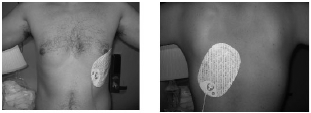
Electrodes, which commonly are self-adhesive pads, are placed on the skin of the anterior and posterior chest wall. (See Figure 4.) If the patient has an implanted pacemaker device, this positioning will ensure that the pacing pads are at least 10 cm away from the pulse generator. These electrodes are connected to a portable pulse generator that also may function as a rhythm monitor and defibrillator. This technique is particularly useful as a stabilization measure in the field or in the ED while preparations are made for transvenous pacemaker insertion. This technique also may be preferable to transvenous pacing in the setting of recent administration of thrombolytic agents when central venous puncture places the patient at risk for hemorrhage.
| Figure 4. Transcutaneous Pacemaker Lead Placement |
|
|
All transcutaneous pacemakers provide some basic features including asynchronous and demand mode pacing, current and rate adjustments, and an integrated monitor. Without the use of this integrated monitor, the electrocardiography monitor often is overwhelmed by the large pacing electrical spike and requires "blanking of the electrical spike" to interpret the ECG complex.18 Once the pacing pads are placed, the rate generally is set at 60-80 beats per minute. Output should be set at the lowest output and increased gradually until capture is confirmed on the cardiac monitor (electrical capture). The average adult usually can be paced with a current of 40-70 mA (transvenous pacemakers capture at less than 1-2 mA). Mechanical capture is determined by the presence of a pulse or cardiac contraction by ultrasound at a rate that corresponds to the set rate on the pulse generator. A study done on 16 healthy male volunteers who were paced without sedation noted cardiac capture at a mean of 54 mA and range was 42-60 mA.26 Most subjects could tolerate pacing at their capture threshold without any sedation or medication, with only one requiring discontinuation due to intolerable pain at 60 mA. Discomfort in this setting most often is related to large muscle contractions associated with the impulse, and incremental doses of opioids and benzodiazepines generally will make the intervention tolerable.
Transcutaneous pacing now is commonplace treatment in the pre-hospital care of patients. Coordinating the type of pacing pads used with your local EMS providers would make patient transition to ED equipment a smoother process.
Transvenous Pacing. Transvenous pacing offers a more definitive means of control of bradydysrhythmias, and although it is more invasive, it is better tolerated than the transcutaneous method in terms of the discomfort the patient may feel with each pacing stimulus. The proper and effective placement of a transvenous pacemaker demands that the emergency physician is comfortable with central line placement, is familiar with the types of transvenous catheters available, and is knowledgeable of the adjustment and operation of the pacing generator.
Contraindications. As with all invasive interventions, the risks of emergent temporary pacing must be weighed against the benefits of the procedure. Severe hypothermia may cause dysrhythmias such as significant bradycardia. Pacing under these circumstances usually is not necessary as the cardiac disturbances usually resolve with rewarming. Furthermore, any stimulation such as pacing may aggravate the hypersensitive myocardium resulting in more worrisome dysrhythmias such as ventricular tachycardia. Concomitant use of thrombolytics during acute MI can be a relative contraindication but does not preclude pacemaker insertion should serious dysrhythmias develop, especially in the setting of hemodynamic compromise. The presence of a prosthetic tricuspid valve is an absolute contraindication to transvenous right ventricular pacemaker insertion.
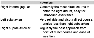
Obtaining Initial Venous Access. A wide area of skin over the venous access site must be prepped with povidone-iodine and draped to minimize the risk for infection. Sterile precautions should be maintained throughout the procedure if possible. An access point through which to pass the transvenous pacer leads must be established first. The choice of this access point is based on which route would provide the most direct approach to entering the heart with the least possibility of being misdirected, most likelihood for successful establishment, and consideration of contraindications. The most common central venous access sites for transvenous pacing in the ED setting are the right internal jugular vein or subclavian vein. (See Table 2.) Studies have found that the right internal jugular approach is associated with the lowest complication rate.27,28 The right supraclavicular approach is a safe alternative.29 There is a risk of deep vein thrombosis using the femoral vein approach, which rarely is used for this purpose in the ED.30 Once a temporary pacemaker is in place, a permanent pacemaker should not be placed on that side due to risk of infection.
|
Table 2. Recommended Access for Transvenous Pacemaker Insertion |
|
|
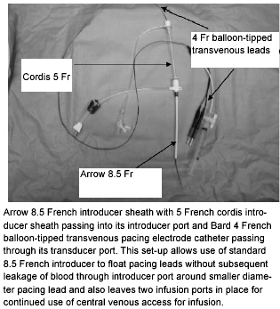
An introducer set or sheath is required for venous access. The introducer set is used to enhance passage of the pacing catheter to the heart. To allow passage of the pacing catheter, the sheath must be at least one size larger than the pacing catheter. Once venous access is obtained and the J-wire has been advanced, insert the introducer catheter in the standard fashion. Unfortunately, the lumen of introducer kits commonly available in the ED is too large (7.5-8 Fr) for commonly used temporary transvenous pacer catheters (4-5 Fr), resulting in leakage of blood around the pacemaker catheter through the introducer lumen. For this reason, an appropriately sized introducer kit should be available with pacemaker supplies and dedicated for this purpose in the ED. If the larger (7.5-8 Fr) introducer is already in place or a smaller sized introducer kit is not available, a makeshift sheath can be made by inserting a 14-gauge, 1.5- to 2-inch angiocatheter or a 5 Fr introducer inside the larger introducer lumen. The pacing catheter then is inserted through the smaller lumen. (See Figure 5.)
|
Figure 5. Modified Introducer Set-up for Transvenous Pacemaker Insertion |
|
|
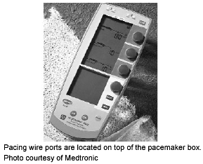
Pulse Generator. Temporary pacemakers are much simpler in design compared to permanent pacemakers as size and longevity are not an issue. Temporary pulse generators are manufactured by a number of companies. They are available in single- and dual-chamber pacing modes. In single-chamber pulse generators, there is one pair of connections for the two pole connections on the pacing wire. Dual pulse generators are more complex and have two pairs of connectors for the two pairs of pacing wires (i.e., atrial and ventricular). An example of a modern dual-chamber pacemaker is illustrated in Figure 6. Transvenous pacing performed emergently in the ED typically is single-chamber pacing. The operator must be familiar with what mode to use on the generator such as VVI for bradycardias or VOI in case of asystole. Temporary generators also have many other adjustable parameters including rate limits, amplitude, and sensitivity. Pulse width or duration usually is fixed as mentioned above and is not a programmable function required in the ED. Each generator generally has a locking mechanism that prevents patients from accidentally adjusting the settings. Most temporary pulse generators use a standard 9-V alkaline battery. The voltage can be increased by special circuitry such that the actual voltage output is approximately 15 V, as opposed to most permanent pacemakers that have a maximum of 5 V. The higher voltage of a temporary pacemaker battery allows pacing at moderately high thresholds if needed. (Pulse generator settings for temporary transvenous pacemaker insertion are discussed on page 18 under "Pacing Catheter Insertion.")
|
Figure 6. Pulse Generator
for Dual-Chamber |
|
|
Pacing Catheters. Several types of pacing catheters are available for temporary transvenous pacing. The sizes range from 2 Fr to 7 Fr in size. The 4 Fr catheter most commonly is used in adults. The catheters are approximately 100 cm in length and are marked at approximately 10-cm intervals that can be used to estimate catheter position during insertion. Electrode catheters can be used to pace the atria or ventricles. However, ventricular pacing is more common in the ED setting. Atrial leads sometimes are used to treat atrial tachycardias such as atrial flutter but more commonly are used to provide AV synchrony if a dual-chamber pacemaker is required. Atrial leads are not inserted when the only indication for pacing is bradycardia. Temporary pacemaker leads are mostly insulated wires that are stiffer than permanent pacemaker electrodes. Disposable temporary pacing leads are preferred as small cracks in the insulation can occur with frequent usage and sterilization. Transthoracic leads also are available, but this method of pacing is rarely, if ever, used in the ED. A cable is used to connect the pacing generator to the leads of the pacing catheter.
There are two basic types of pacer catheters, the floating or balloon tip and the semi-floating type. If the patient has some forward blood flow, it is less traumatic to the myocardium and vessel wall to let the balloon move the pacer tip into position. If the clinical situation is more precarious and there is no forward blood flow, the semi-floating catheter may be a better choice to allow the clinician to mechanically push the catheter through the tricuspid valve and into the right ventricle. When using a floating catheter, the balloon can be inflated with 1.5 mL of air, which usually is maintained with a locking device attached to the catheter. The balloon should be checked for air leakage prior to insertion by immersing the inflated balloon in sterile water. The appearance of bubbles at the surface of the water is concerning for the presence of an air leak. An inflated balloon helps the catheter float into the heart in low flow states. The lack of spontaneous circulation (i.e., cardiac arrest) obviates the use of this technique. Some pulmonary artery catheters31 used for hemodynamic monitoring having pacing capability. Unfortunately, inflating the balloon to measure pulmonary artery wedge pressure may cause the electrodes to migrate out of their pacing position. This form of pacing is less stable than other transvenous catheters and should not be used if the patient is pacemaker dependent. Furthermore, this capability is unlikely to be available in most EDs.
Differentiating ventricular wires from atrial wires, and positive electrodes from negative electrodes, is simplified in patients with transvenous or pulmonary artery catheter pacemakers where the pacing wires are threaded directly into the chambers of the right atrium and right ventricle using the appropriate prelabeled ports. Each pair of wires (atrial or ventricular) has one positive lead and one negative lead (commonly the shorter of the two wires) that is connected to the pulse generator; however, this may vary among institutions. Single-chamber ventricular pacing is more commonly performed in the ED.
Both bipolar and unipolar systems are available. Temporary transvenous pacing in the ED usually involves a bipolar catheter. A bipolar pacemaker easily can be converted to a unipolar pacemaker by connecting the distal or proximal electrode to the negative pole of the pacemaker generator. The tip of the other electrode is unused and should be covered with a rubber glove to prevent a short-circuit of the pacing unit. The positive pole of the pacemaker generator is connected to a wire suture, needle, or metal plate that is in firm contact with the skin of the patient.
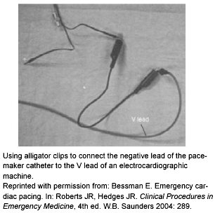
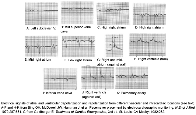
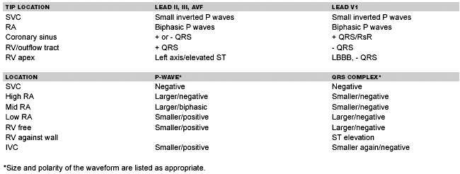
Pacing Catheter Insertion. After obtaining central venous access with the introducer set, a modified Seldinger technique is used to place the electrode catheter. Transvenous pacing typically is performed blindly or using ECG monitoring as a guide. ECG monitoring during insertion is a readily available means of monitoring for capture and approximating positioning at the bedside. To use ECG monitoring, connect the limb leads of the 12-lead ECG machine to the patient and connect one of the precordial leads (V leads) to the negative terminal of the pacer wire (distal terminal). An alligator can be used to establish the connection between the V lead and the pacer wire. (See Figure 7.) As the wire is advanced, characteristic waveforms will appear on the ECG tracing as summarized in Table 3 and Figure 8. Fluoroscopy often is used by cardiologists but is not practical or available in most EDs. In patients with spontaneous circulation, the use of a floating catheter was found to be more expeditious and stable than the fluoroscopy-guided technique when performed by emergency physicians.32
| Figure 7. Use of Alligator Clips for ECG Guidance | Figure 8. Intracardiac Electrocardiography |
|
|
|
| Table 3. Using ECG Guidance in Transvenous Pacemaker Insertion |
 |
Recently, transvenous pacemaker insertion has been added to the many applications of bedside ultrasound in the ED setting.10,33-36 Pacing catheter wires reflect ultrasound waves and are visible within the cardiac chambers as bright linear echoes. The subcostal window provides the best view of all the cardiac chambers for a patient in the supine position. Successful insertion is evidenced by the visualization of the pacing wire in the apex of the right ventricle with electrical capture and a positive hemodynamic response. Ultrasound also has the added benefit of detecting pericardial fluid and allows global evaluation of heart wall motion. This is of particular importance in determining the presence of ventricular contractions in patients who do not have a detectable pulse or blood pressure.37 The use of ultrasound may be limited in patients who are obese and have chronic obstructive pulmonary disease as fat and air act as ultrasound barriers, making visualization difficult.
If the balloon-tip catheter is chosen, pass the catheter through the sheath and at about the 10 cm mark, inflate the balloon and advance slowly. Attach the electrodes (i.e., wires) to the pacer generator and move the catheter distally looking for capture evidence. The catheter has markings every 10 cm delineated by dark lines, and prior to insertion it helps to look at the patient's body habitus from insertion site to where the right ventricle might be and benchmark this distance as that point where the marks would be at the sheath's proximal aspect.
If time permits and the patient has some forward flow, place the generator in the sense mode and advance until cardiac activity is sensed then switch to pace mode. If there is no intrinsic cardiac activity, the pace mode should be used as the sensing mode will be ineffective. Adjust the output current to 15-20 mA and, once capture is noted, decrease this output to the lowest possible level that will maintain capture. If capture is not achieved, withdraw back 10 cm and re-advance, increasing the output if necessary. When reaching a depth of approximately 15 cm, having the patient turn to the left side and cough may help facilitate entry into the ventricle by keeping the tricuspid valve open for a longer duration. Once a perfusing capture rhythm is attained, secure the remaining pacer catheter not protected to the chest wall with a sterile dressing over the sheath and insertion site. To ensure adequate sensing and capture, the pacemaker output should be set at least two to three times the pacing threshold and two to three times the sensing threshold. The pacing threshold in the right ventricle is typically less than or equal to 1 mA. The rate should be set at 80. The initial sensitivity setting should start at 2-5 mV. If failure to sense occurs (i.e., intrinsic impulses are not recognized), turn the patient on the left side to improve contact between the electrode and myocardium. If this is unsuccessful, then the sensitivity must be increased by turning down the millivoltage to allow the generator to detect beats that occur at lower millivolt levels. If the pacer is sensing beats that are not actually present, the sensitivity threshold must be increased to block out artifact. This is accomplished by turning the sensitivity up.
Confirmation of Placement. Once the catheter is secured and the patient is stabilized, obtain a chest x-ray and a 12-lead electrocardiogram. The endoventricular lead should be at the right ventricular apex. When the pacemaker catheter is in proper position, the QRS should have a left bundle branch morphology immediately following the pacing spike, indicating capture. (See Figure 1.)
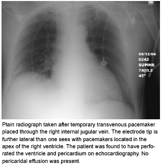
Complications. Temporary transvenous pacing is a relatively safe procedure when performed by an individual trained in the procedure. Placement of transvenous leads during emergency circumstances increases the risk of the procedure. Complications include inadvertent arterial puncture, pneumothorax, hemothorax, air embolism, serious bleeding, perforation of the interventricular septum, atrial or ventricular myocardial perforation, cardiac tamponade, pericardial friction rub, phrenic nerve injury, thoracic duct injury, guidewire fracture, dysrhythmias, lead dislodgement, loss of capture or sensing ability infection, and thromboembolism resulting in pulmonary embolism particularly if the femoral vein is used.25,27,38-42 Figure 9 illustrates a plain radiograph of a patient with a ventricular perforation after temporary transvenous pacemaker placement.
| Figure 9. Ventricular Perforation Due to Temporary Transvenous Pacemaker Placement |
|
|
Other Types of Temporary Pacing
There are other possible alternatives for temporary pacing other than transvenous and transcutaneous techniques described above. Atrial and ventricular leads may be placed in patients undergoing cardiac surgery. Transthoracic insertion via a needle placed directly through the chest wall is an option but rarely is performed. Placement of an esophageal electrode has been used successfully but primarily is indicated for atrial pacing and recording.
Conclusion
Emergency physicians may be confronted with a variety of emergency pacing situations. It is important that these physicians be familiar with basic pacemaker technology, terminology, and trouble-shooting techniques for a malfunction. Temporary emergency pacing may be required in the ED for bradyarrhythmias or tachyarrhythmias that may cause hemodynamic compromise. All EDs should be equipped to handle such emergencies with a transcutaneous pacemaker and transvenous pacemaking kit as well as with individuals who are capable of performing these potentially life-saving interventions.
References
1. Furman S. The early history of cardiac pacing. Pacing Clin Electrophysiol 2003;26:2023-2032.
2. Luderitz B. The History of the Disorders of Cardiac Rhythm: Blackwell Publishing; 2002.
3. Abinader EG, Sharif D, Malouf S, et al. Temporary transvenous pacing: analysis of indications, complications and malfunctions in acute myocardial infarction versus noninfarction settings. Isr J Med Sci 1987;23(8):877-880.
4. Zoll PM. Resuscitation of the heart in ventricular standstill by external electric stimulation. N Engl J Med 1952;247:768-771.
5. Weirich WL, Gott VL, Lillehei CW. The treatment of complete heart block by the combined use of a myocardial electrode and an artificial pacemaker. Surg Forum 1957;8:360-363.
6. Callaghan JC, Bigelow WG. An electrical artificial pacemaker for standstill of the heart. Ann Surg 1951;134:8-17.
7. Swan H, Ganz W. Catheterization of the heart in man with use of a flow-directed balloon tipped catheter. N Engl J Med 1970;283:447.
8. Moses HW, Miller BD, Moulton KP, et al. A Practical Guide to Cardiac Pacing. 5th. ed. Philadelphia: Lippincott Williams & Wilkins; 2000.
9. Ettin D, Cook T. Using ultrasound to determine external pacer capture. J Emerg Med 1999;17:1007-1009.
10. Holger JS, Lamon RP, Minnigan H, et al. The Use of Ultrasound to Determine Ventricular Capture in External Cardiac Pacing. Acad Emerg Med 2001;8:544-.
11. Tam MM. Ultrasound for primary confirmation of mechanical capture in emergency transcutaneous pacing. Emerg Med (Fremantle) 2003;15:192-194.
12. Stone KR, McPherson CA. Assessment and management of patients with pacemakers and implantable cardioverter defibrillators. Crit Care Med 2004;32(4 Suppl):S155-S165.
13. Weinberger BM, Brilliant LC. Pacemaker and automatic internal cardiac defibrillator. eMedicine.com, Inc. Last updated: June 8, 2005. Accessed 12/12/2005 at http://www.emedicine.com/emerg/topic805.htm.
14. Abraham WT. Cardiac resynchronization therapy for heart failure: biventricular pacing and beyond. Curr Opin Cardiol 2002;17:346-352.
15. Hayes DL, Vlietstra RE. Pacemaker malfunction. Ann Intern Med 1993;119:828-835.
16. Niemann JT. Implantable cardiac devices. 5th ed. St. Louis: Mosby; 2002.
17. Hazard PB, Benton C, Milnor JP. Transvenous cardiac pacing in cardiopulmonary resuscitation. Crit Care Med 1981;9:666-668.
18. Bessman E. Emergency Cardiac Pacing. 4th ed. ed. Philadelphia, PA: Saunders; 2004.
19. Syverud SA, Dalsey WC, Hedges JR. Transcutaneous and transvenous cardiac pacing for early bradyasystolic cardiac arrest. Ann Emerg Med 1986;15:121-124.
20. Goldberg R, Zevallos JC, Yarzebski J, et al. Prognosis of acute myocardial infarction complicated by complete heart block (the Worcester Heart Attack Study). Am J Cardiol 1992;69:1135-1141.
21. Bognolo D, Rabow R, Bijayanagar R, et al. Traumatic sinus node dysfunction. Ann Emerg Med 1982;11:319.
22. Atkins J, Leshin S, Blumquist G, et al. Ventricular conduction blocks and sudden death in acute myocardial infarction. N Engl J Med 1978;288:281.
23. Hindman H, Wagner G, JaRo M, et al. The clinical significance of bundle-branch block complicating acute myocardial infarction. 2. Indications of temporary and permanent pacemaker insertion. Circulation 1978;58:689.
24. Resuekov L, Lipp H. Pacemaking in acute myocardial infarction. Prog Cardiovasc Dis 1972;14:475.
25. Goldschlager N. Conduction disorders & cardiac pacing. In: Current Diagnosis and Treatment in Cardiology, 2nd Edition. New York: Lange Medical Books/McGraw-Hill; 2002; 292-323.
26. Falk RH, Zoll PM, Zoll RH. Safety and efficacy of noninvasive cardiac pacing. A preliminary report. N Engl J Med 1983;309:1166-1168.
27. Hynes JK, Holmes DR, Jr., Harrison CE. Five-year experience with temporary pacemaker therapy in the coronary care unit. Mayo Clin Proc 1983;58:122-126.
28. Syverud SA, Dalsey WC, Hedges JR, et al. Radiologic assessment of transvenous pacemaker placement during CPR. Ann Emerg Med 1986;15:131-137.
29. Laczika K, Thalhammer F, Locker G, et al. Safe and efficient emergency transvenous ventricular pacing via the right supraclavicular route. Anesth Analg 2000;90:784-789.
30. Nolewajka AJ, Goddard MD, Brown TC. Temporary transvenous pacing and femoral vein thrombosis. Circulation 1980;62:646-650.
31. Swan H, Ganz W. Catheterization of the heart in man with use of a flow-directed balloon tipped catheter. N Engl J Med 1970;283:447.
32. Lang R, David D, Klein HO, et al. The use of the balloon-tipped floating catheter in temporary transvenous cardiac pacing. Pacing Clin Electrophysiol 1981;4:491-496.
33. Aguilera PA, Durham BA, Riley DA. Emergency transvenous cardiac pacing placement using ultrasound guidance. Ann Emerg Med 2000;36:224-227.
34. Holger JS, Lamon RP, Minnegan HJ, et al. Use of ultrasound to determine ventricular capture in external cardiac pacing in an animal model. Acad Emerg Med 2000;7:454-a.
35. Meier B, Felner JM. Two-dimensional echocardiographic evaluation of intracardiac transvenous pacemaker leads. J Clin Ultrasound 1982;10:421-425.
36. Macedo W, Jr., Sturmann K, Kim JM, et al. Ultrasonographic guidance of transvenous pacemaker insertion in the emergency department: a report of three cases. J Emerg Med 1999;17:491-496.
37. Blaivas M, Fox JC. Outcome in cardiac arrest patients found to have cardiac standstill on the bedside emergency department echocardiogram. Acad Emerg Med 2001;8:616-621.
38. Jafri SM, Kruse JA. Temporary transvenous cardiac pacing. Crit Care Clin 1992;8:713-725.
39. Wald D. Therapeutic procedures in the emergency department patient with acute myocardial infarction. Emerg Med Clin North Am 2001;19:541-566.
40. Jowett NI, Thompson DR, Pohl JE. Temporary transvenous cardiac pacing: 6 years experience in one coronary care unit. Postgrad Med J 1989;65:211-215.
41. Austin JL, Preis LK, Crampton RS, et al. Analysis of pacemaker malfunction and complications of temporary pacing in the coronary care unit. Am J Cardiol 1982;49:301-306.
42. Foo NP, Lin HJ. Delayed perforation of right ventricle with cardiac tamponade: A complication of pacemaker implantation. Eur J Emerg Med 2005;12:89-91.
A pacemaker is an electronic device that provides an electrical signal to stimulate the heart beat when the intrinsic pacemakers fail. The development and implementation of cardiac pacing and pacemaker generators has been well described and documented in many publications.Subscribe Now for Access
You have reached your article limit for the month. We hope you found our articles both enjoyable and insightful. For information on new subscriptions, product trials, alternative billing arrangements or group and site discounts please call 800-688-2421. We look forward to having you as a long-term member of the Relias Media community.

